
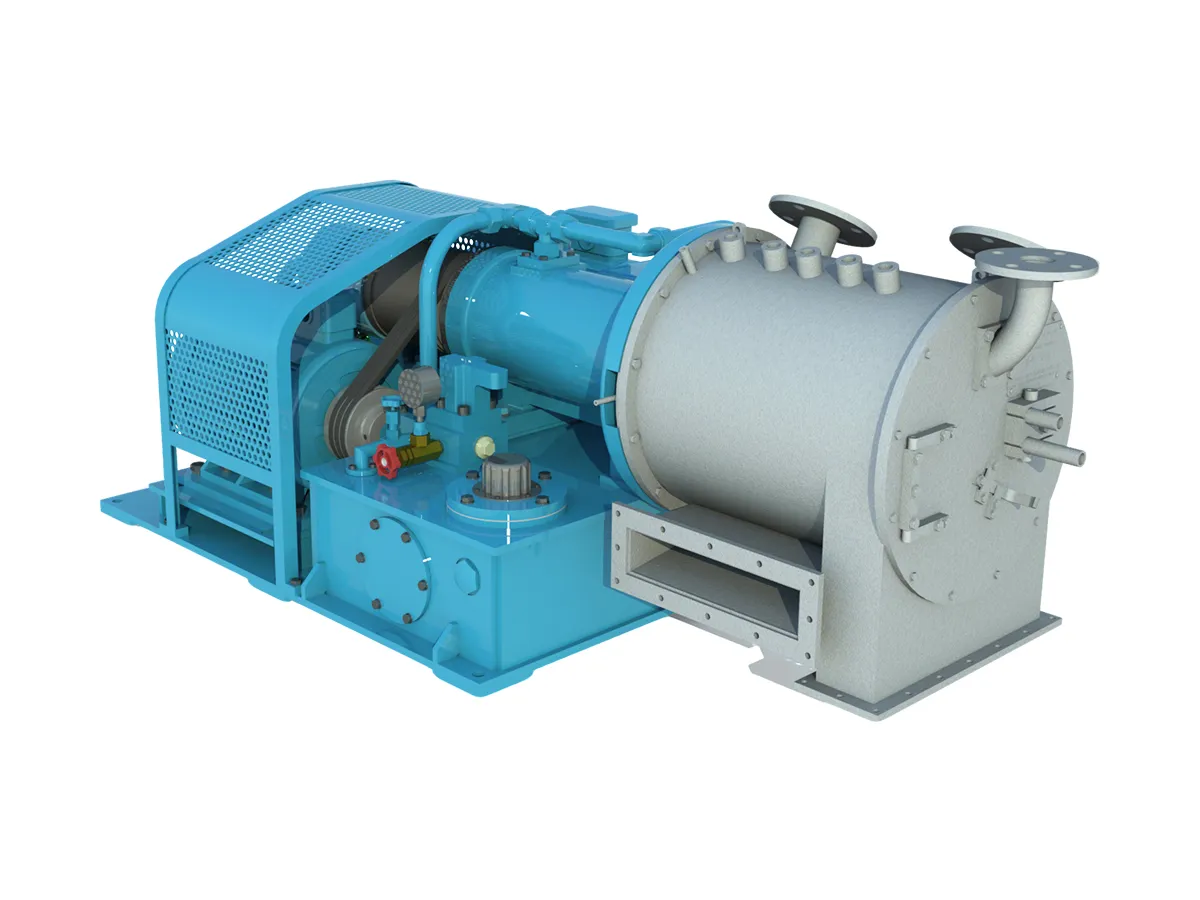
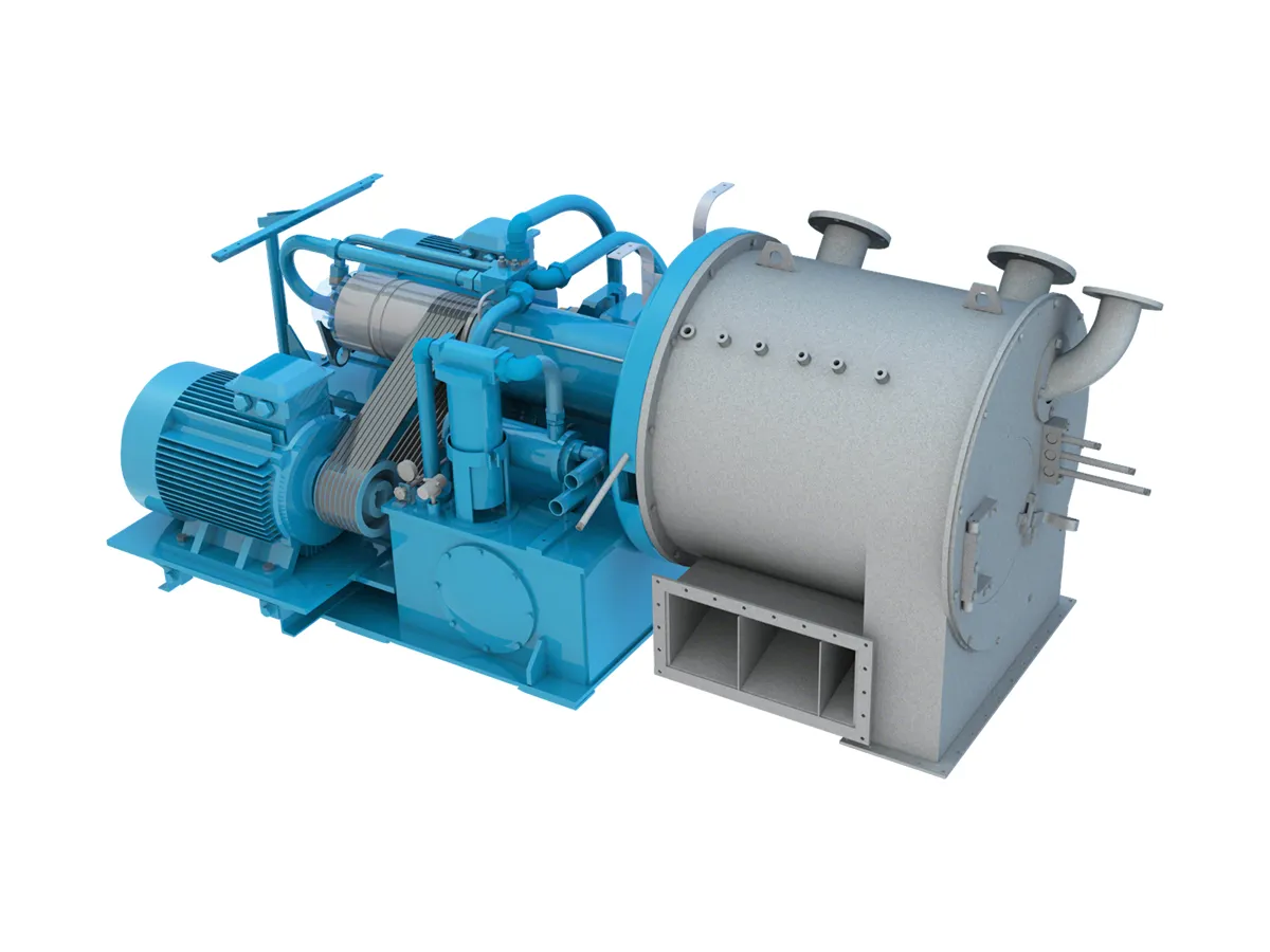
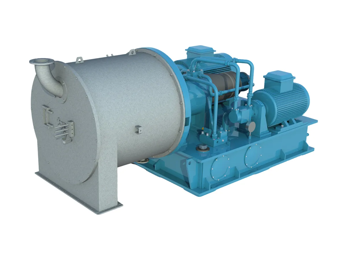
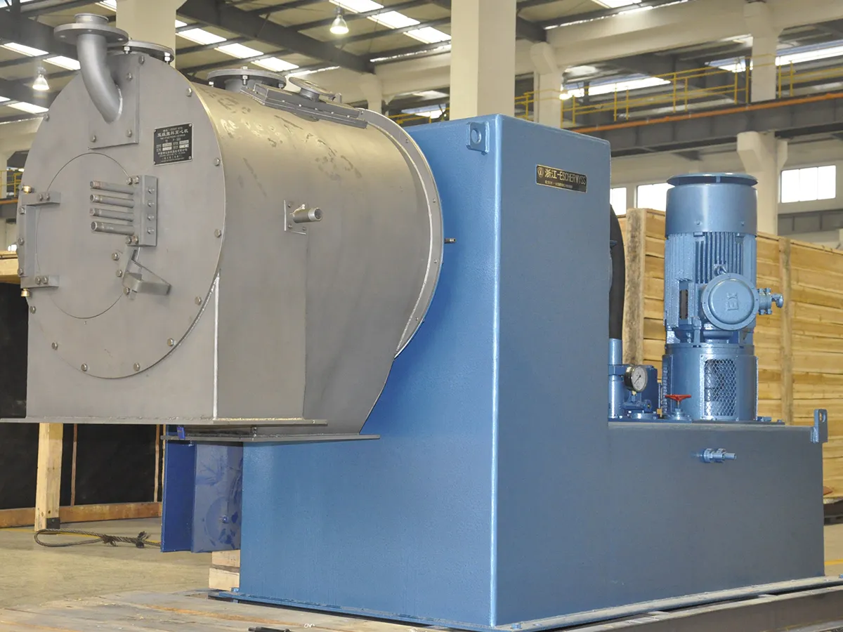
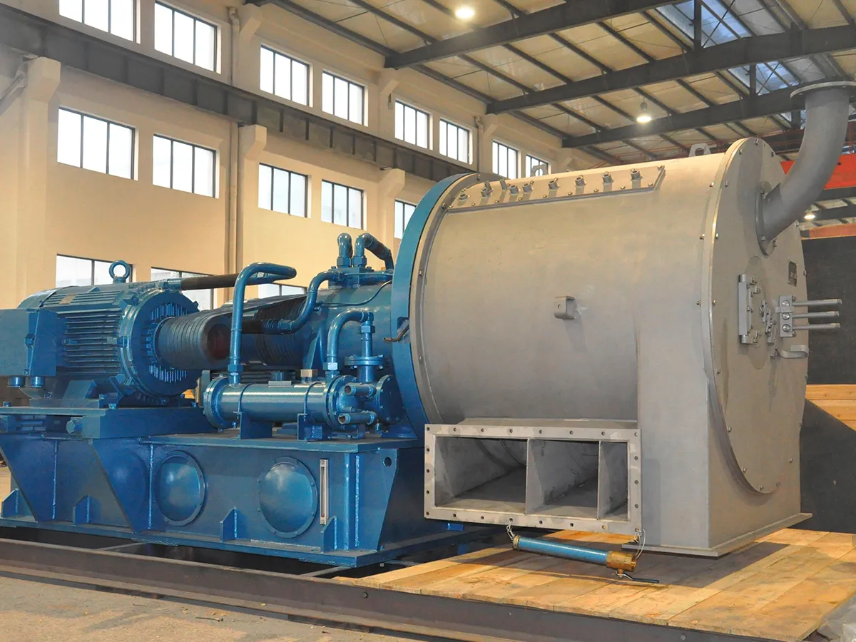
Two-Stage Pusher Centrifuge
- Basket Diameter (mm) 200/251 - 1,118/1,204
- Pusher Frequency (strokes/min) 20-90
- Max. Speed (r/min) 900-3,000
- Throughput (t/h, Vacuum Salt Production) 1.5-80
The two-stage pusher centrifuge is a continuous, high-efficiency filtration centrifuge that performs feeding, filtration, washing, dewatering, and discharge in a single cycle. Its two-stage cylindrical drum design transports the material through continuous dewatering throughout both stages: the first stage typically separates around 70% of the liquid from the suspension, while the second stage removes the remaining moisture and produces a uniform, consistent filter cake.
The two-stage system increases the effective centrifugal dewatering time. As the cake moves from the first to the second drum, it loosens again, reopening the filtration path through the second stage, increasing separation efficiency and decreasing cake moisture. An optional wash pipe removes contaminants from the material, ensuring that the separated product meets purity criteria. The machine is suitable for continuous dewatering and washing of granular and fibrous suspensions with particle size ≥ 50 μm.
| Model | Basket Diameter (mm) | Pusher Frequency (strokes/min) | Max. Speed (r/min) | Hydraulic Fluid Operating Pressure (MPa) | Main Motor Power (kW) | Hydraulic Pump Motor Power (kW) | Throughput (t/h, Vacuum Salt Production) | Overall Dimensions (mm, L*W*H) | Machine Weight (kg) |
| 200/251 | 20-50 | 3,000 | 3 | 7.5 | 4 | 1.5 | 1,870*860*640 | 800 | |
| 290/360 | 55-75 | 2,500 | 2.5 | 11-15 | 5.5-7.5 | 5 | 2,386*1,334*1,121 | 2,600 | |
| 330/400 | 55-75 | 2,200 | 2.5 | 11-15 | 5.5-7.5 | 6 | 2,386*1,334*1,121 | 2,650 | |
| 438/500 | 60-80 | 2,000 | 2 | 37-55 | 18.5-22 | 15 | 3,600*1,420*2,078 | 4,300 | |
| 486/550 | 70-90 | 1,700 | 4 | 30-45 | 15-22 | 18 | 2,580*1,632*1,325 | 3,760 | |
| 550/630 | 70-90 | 1,400 | 4 | 30-45 | 15-22 | 25 | 2,596*1,688*1,380 | 3,860 | |
| 560/630 | 60-80 | 1,900 | 8 | 45-55 | 22-30 | 30 | 3,445*1,965*1,930 | 4,860 | |
| 738/820 | 40-80 | 1,500 | 8 | 75-90 | 37-45 | 45 | 3,990*2,162*2,063 | 8,050 | |
| 920/1,000 | 50-70 | 1,300 | 10 | 75-132 | 55-75 | 65 | 4,330*1,840*1,965 | 10,500 | |
| 1,118/1,204 | 50-70 | 900 | 10 | 90-132 | 75-90 | 80 | 4,354*1,987*1,847 | 11,200 |
- Chemical Industry: Traditional vacuum salt production, alkali production, and chemical intermediates.
- Pharmaceutical Industry: Separation of intermediates and excipients.
- Environmental Protection: Crystallization of inorganic salts in industrial wastewater treatment.
- Mineral processing: Mineral purification and crystallization separation.
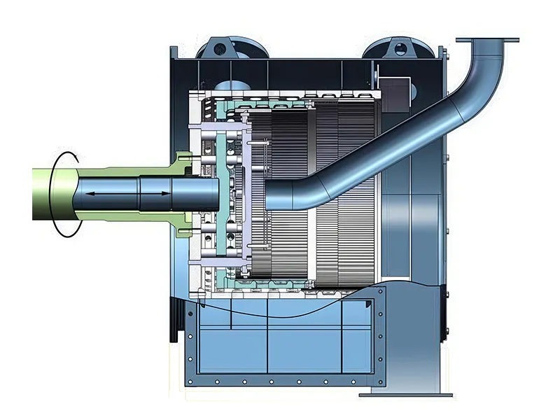
Once the drum reaches maximum speed, the suspension is fed continuously through the feed pipe to the distribution plate. The solid phase is retained on the screen as an annular cake layer by the centrifugal field, which distributes it uniformly across the screen within the drum. The cake is progressively expelled from the drum by the reciprocating motion of the first-stage drum, which discharges it through the casing's discharge channel.
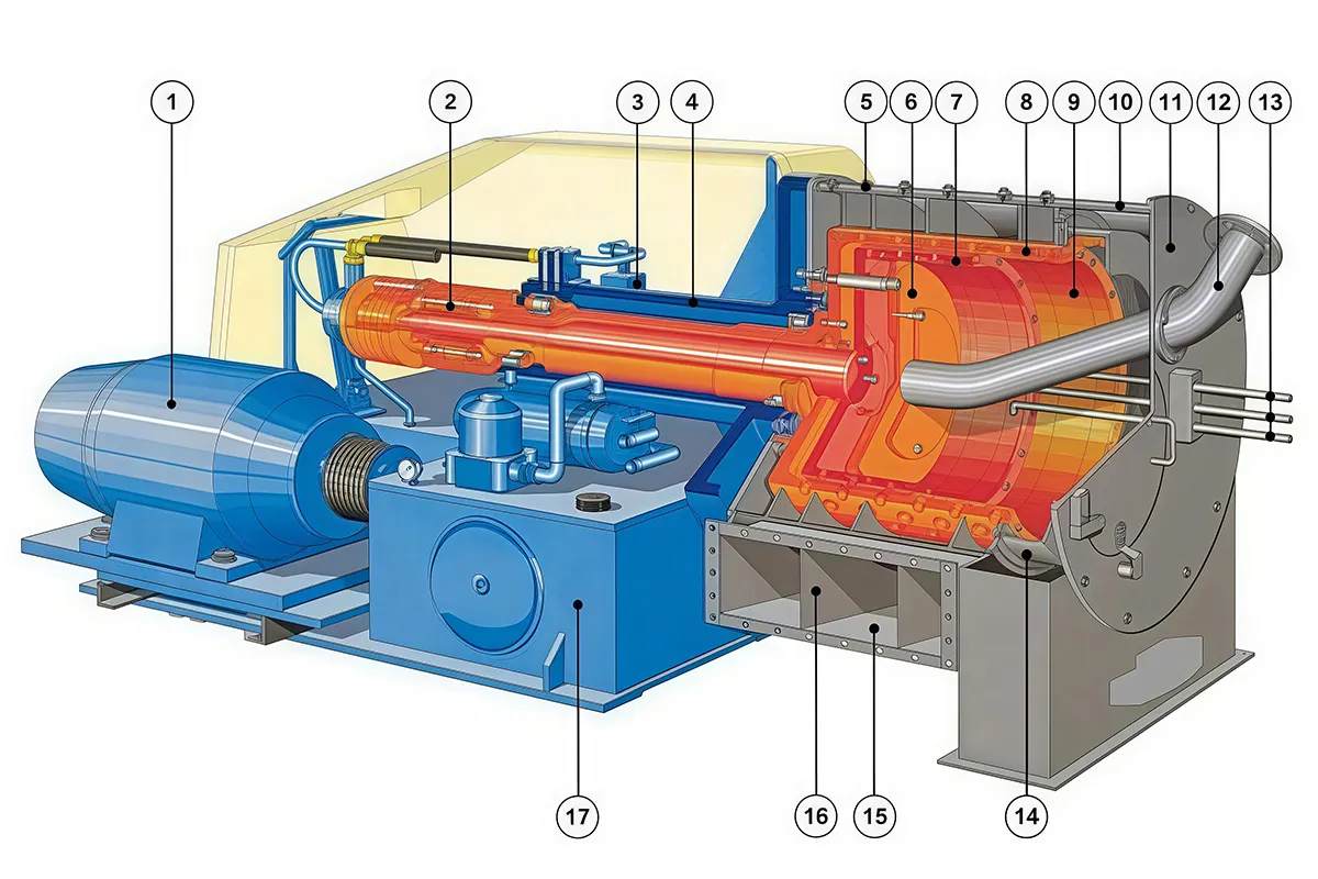
- Main motor
- Reversing mechanism
- Oil distribution housing
- Bearing housing
- Casing
- Feed distribution plate mechanism
- First-stage drum mechanism
- Second-stage drum assembly
- Screen
- Discharge chamber
- Front cover assembly
- Feed pipe assembly
- Washing/rinsing assembly
- Solids discharge chute assembly
- Liquid outlet
- Liquid baffle/partition
- Machine base
 Rotating Drum
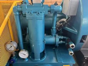 Oil Filter and Cooler
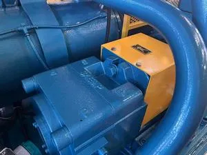 Oil Pump
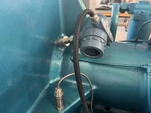 Bearing Temperature and Vibration Sensors
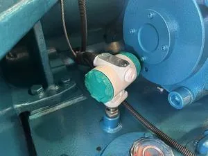 Oil Temperature Sensor
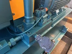 Pressure Sensor
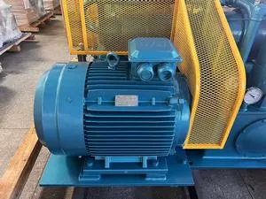 Main Motor
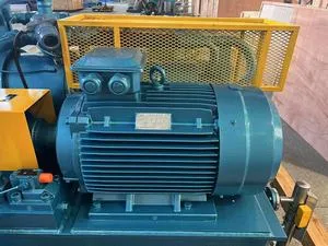 Oil Pump Motor
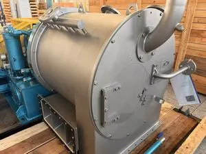 Casing and Front Cover Plate